The Design & Construction of Alacazam: A Wood Epoxy Sailboat
Building our 38-foot one-off cruising sailboat, Alacazam, from scratch was a monumental undertaking that took us from constructing a temporary shed to launching a stunning yellow and white sailboat. This article chronicles that journey, sharing our real-world experience of building a wood-epoxy cedar-strip sailboat. You'll discover how a simple building technique and careful planning can create a strong, beautiful, and enduring offshore cruising vessel, proving that the right approach can turn a complex project into a personal success story.
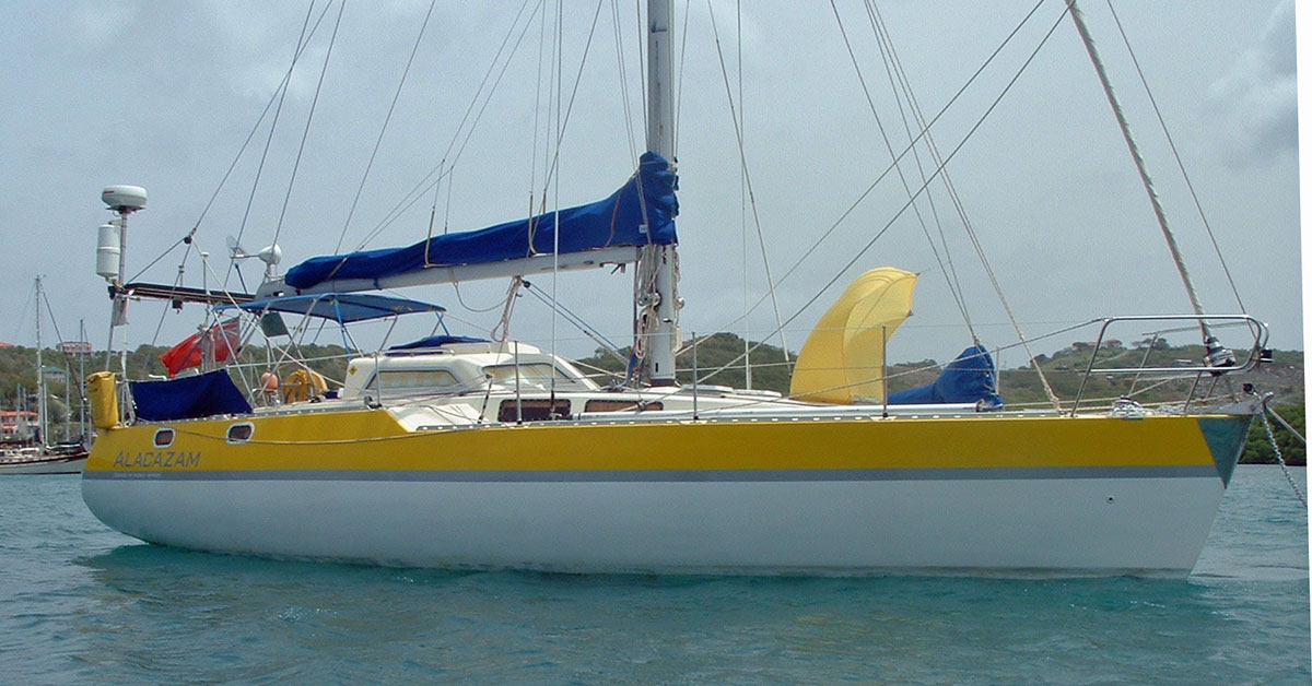 Several years after Alacazam's conception and a successful two-handed Atlantic crossing. Though I say it myself, she's a handsome sailboat.
Table of Contents
Jumping forward several years...
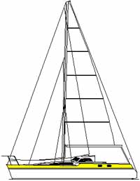 Designers sketch of Alacazam
She was called 'Alacazam', from the great Nat King Cole's song Orange Coloured Sky, and these are her vital statistics...
- Length overall: 11.5m (37.5 feet)
- Waterline length: 10.6m (34.5 feet)
- Beam: 3.9m (12.5 feet)
- Draft: 2.2m (7 feet)
- Displacement: 7,023kg (7.75 tons)
- Displacement/length ratio: 159
- Sail area/displacement ratio: 18.28
First, you need a Plan...
Of course you don't have to start from scratch as we did; there are a few other boat building options available that could save time and maybe cash too. For instance you could buy an old, tired boat and completely refurbish her, but we wanted something special, unique to us and different.
Whichever option you choose it's a very good idea to think the whole project through from beginning to end, as nothing can cause more disruption and additional cost than changing your mind halfway through a sailboat construction project such as ours.
It's an inescapable fact that cost and size are closely related, but not in a linear fashion as you might assume. If you double the length of the boat you're likely to increase the costs by a factor of four; and not just the build costs, but owning and operating costs too. Just wait until anti-fouling time comes around and you'll see what I mean.
Berthing costs seem to take a hike at around 12m (40ft) overall, and another at 15m (50ft), which was the final compelling factor in sizing our self-build cruising sailboat at 11.5m (38ft) on deck. This allowed for the anchor poking out at one end and the self-steering gear at the other, just in case any marina employee should get overzealous with the tape measure.
The Outline Requirements for our 'Ideal Cruising Sailboat'
My current boat at the time was a Nicholson 32 Mk10 called Jalingo II. She was a narrow hulled, heavy displacement, long keeled cruiser that I'd sailed thousands of miles—much of it singled handed (until I met Mary, who put paid to all of that self-indulgence)—off the shores of the UK and France, then across the notorious Bay of Biscay to Spain and Portugal, and on to the Mediterranean and back to the UK.
Her hull shape and displacement (Jalingo's, not Mary's) meant that she was comfortable in a seaway and great in a blow, but sluggish in light winds - and that keel meant she was a nightmare to handle in the confines of a marina.
Like all long-distance sailors I had a good idea as to what my 'ideal cruising sailboat' would be. I've always thought that a cutter rigged sloop is the ideal the ideal rig for a cruising boat, with a roller furling jib, a hanked-on staysail (easy to replace with a storm jib when necessary) and a slab-reefing mainsail with lazy jacks, as I don't trust either in-mast or in-boom furling contraptions.
And our days of heavy displacement and long keels were over; our new boat would be light-to-medium displacement with a fin keel and skeg-hung rudder.
We thought long and hard about whether she was to be tiller or wheel steered, but we eventually went for a tiller—and here's why...
Additionally she would:
- have high resistance to capsize;
- be robust and easy to maintain;
- have good performance under sail;
- have a comfortable, easy motion underway;
- be easily manageable by a small crew;
- have sufficient internal volume for comfortable living aboard;
- be affordable to own and operate.
Did we know how to build a boat with these desirable characteristics? No, but we knew a man who did. Enter Andrew Simpson, yacht designer, surveyor and shipwright - and one of my best chums...
The Designer's Proposals for our Ideal Cruising Sailboat
We discussed all this at length, and made a endless sketches of the layout both above and below deck.
Andrew did the number crunching and came up with an outline design for a 38ft (11.5m) cutter rigged wood/epoxy (cedar strip) water-ballasted cruising boat.
"She'll be light, quick, robust and comfortable" he said
"And seaworthy?" we asked
"Eminently so" he replied
"Right" we said, "Let's do it!"
And so we did...
First Things First...
As a custom-designed one-off sailboat, Alacazam had been designed specifically to meet our requirements for long-distance sailing, and living aboard for extended periods.
She would be of medium-to-light displacement, robust, easily handled by a cruising couple—and reasonably quick.
But first we had to build a construction shed...
We won't dwell too long on the shed construction; suffice to say that the uprights were made of 4" by 4" (100mm x 100mm) timber, the trusses of 6" by 1" (150mm x 25mm), the ridge beam of 6" x 2" (150mm x 50mm) and the gusset plates cut from half inch (12mm) ply.
Diagonal wind bracing was incorporated in the ends of the structure to prevent the whole shebang from collapsing in the first stiff breeze.
Rather than concreting the uprights in pits we built plywood boxes around the bases of the uprights and drove steel pins down into the ground within the boxes.
These were then filled with concrete—that shed was never going anywhere...
Finally we clad it in heavy duty reinforced polythene sheeting, with roll-up 'doors' at each end.
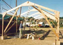 The shed takes shape...
That's it—no more about the shed. We can, in fact, draw a line under it...
Next, the Stillage
This is the rigid structure supporting the temporary frames upon which Alacazam's hull would be built.
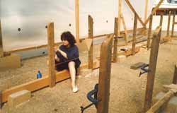 Mary had dark hair before we started...
It had to be absolutely secure, or the hull frames could end up out of alignment—which would have been less than ideal...
The longitudinal timbers were 8" x 4" (200mm x 100mm) timbers held in place by the same concrete block and steel pin technique that we used for the shed.
Before fixing the frames, the centreline was marked on all the horizontal crosspieces using a theodolite, and a horizontal plane on all the uprights with an engineers' level.
Great care had been taken to ensure the uprights were truly vertical and spaced at 1m intervals—and you'll see why this is so important very soon.
Making the Temporary Frames
Alacazam's designer, Andrew Simpson—a man who knows exactly how to build a sailboat, having designed and built several others before this one—developed the hull lines and hydrostats with Vacanti's 'Prolines' design software and created the construction drawings with 'AutoCad'.
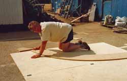 The designer on his knees again
This package generated coordinates at various cross-sections at 1m intervals (stations) along the length of the hull, and enabled us to mark out full-size templates for the temporary frames on sheets of chipboard.
Making due allowance for the hull thickness, we cut out the templates with a jigsaw and assembled them—glued and screwed—into full-size frames.
Both the centreline and the design waterline were marked on each one, along with the station reference number.
Completing the Stillage
The next stage was to fix the temporary frames to the stillage uprights, preferably in the correct order.
The frames were aligned with the centreline marked on the horizontal crosspieces, and levelled such that the marked waterline was a fixed distance from the horizontal plane marked on the uprights. Every frame was checked and double-checked for level and alignment before being fixed firmly in position.
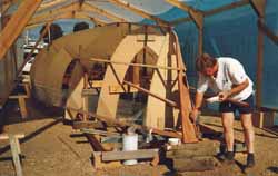 Almost ready to start planking the hull...
The stem was fashioned from a section of solid mahogany, to which the forestay chainplate would be bolted.
This would eventually have a shaped section of mahogany bonded to it, forming the bow and which would offer some protection to the chainplate in the event of collision.
It was to a degree sacrificial in the event of a 'coming together', but hopefully it wouldn't come to that.
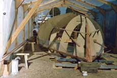
Now we could see what Alacazam's hull with its pronounced tumblehome would really look like, albeit the wrong way up. What's tumblehome? It's the section of the hull which curves upward and inward towards the centreline.
The shed together with the mysterious goings-on inside created a great a deal of interest in the boatyard. Several curious passersby couldn't resist a peep inside, one of which was kind enough to point out that "it wasn't a good idea to build a boat with chipboard", referring to the temporary frames around which Alacazam's hull was to be built.
"But it's marine grade chipboard", we told him. He seemed happy with that explanation and continued on his way. Clearly it was time to start building...
Cedar Strip Boat Building & the Wood-Epoxy Technique
Why did we use the cedar strip boat building technique to build our cruising sailboat Alacazam? For three main reasons—the superior qualities of cedar as a boat building material, the speed of construction of the cedar strip boat building technique, and the strength and lightness of a wood-epoxy hull.
Cedar is a light dimensionally stable wood, with a very high strength-to-weight ratio. It doesn't absorb water readily and is highly resistant to decay, so the common enemy of most other boat building timbers—rot—is not an issue.
It really is an exceptional wood for boat building. Cedar is a sustainable resource, produced in managed forests, so those of us with a care for the environment can build our boats with a clear conscience.
Not sure if the same can be said about epoxy resins though. Oh well...
Planking the Hull in Western Red Cedar
So with the shed complete and the stillage and frames accurately set up, lined and levelled we were ready to get going with cedar strip boat building.
Well almost, but first we had to make the planks.
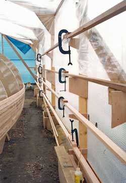 Scarfing cedar strip planks.
We could have bought them already made, but chose to save a few pounds by making our own from 4" x 2" (100mm x 50mm) rough sawn cedar timbers.
Afterall, we had the resources; Andrew's workshop which boasted amongst other essential stuff a bandsaw and a planer-thicknesser.
We soon had produced a good supply of 2" x 1" (50mm x 25mm) cedar strips, which we scarfed together into full hull-length planks.
They were scarfed at a ratio of 8:1, epoxy glued, clamped and stacked on brackets on the shed uprights. Finally we were ready to go...
Mixing the Epoxy Resin
Epoxy resin is supplied in two packs:
- Type A, which is the resin itself, and
- Type B, which is the hardener
On its own, each type is stable but when mixed together in the proportions recommended by the manufacturer they react and start to 'go off', becoming an immensely strong bonding agent, or glue.
To this concoction we added a high density structural filler and mixed it thoroughly. The result was a very sticky 'gloop' which would bond the planks together and fill any voids. Talking of which, avoid getting this stuff on your skin; it's not good—you should always wear disposable rubber gloves when mixing and applying it.
Planking Up
The hull was built upside down, with the first plank—the one at the top of the hull—permanently screwed and epoxy glued to the mahogany stem and temporarily screwed to each frame through to the one at the transom.
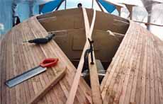
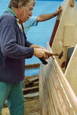 Planking up the hull using the wood epoxy technique and western red cedar strip planks.
The next and subsequent planks are epoxied to the one preceding it, and secured to the plank below it with a dowel pin.
These were cut to length from wooden barbecue skewers, and were driven into holes drilled vertically into the planks between the frames.
We must have cut thousands of them.
The screws were removed once the epoxy gloop had set, but the dowels were of course left in.
As the planking progressed and the curvature of the hull became more pronounced, so we used 1" x 1" (25mm x 25mm) planks to make bending them into position easier.
The edges of the temporary chipboard frames are covered with a strip of polythene to prevent the epoxy doing what epoxy does best.
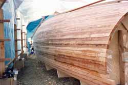 The completed cedar strip hull ready for fairing and sheathing.
Now with the planking complete and the screw holes plugged with epoxy, we ready for the next stage of cedar strip boat building; fairing the hull and sheathing it with epoxy and woven glass rovings.
Sheathing the Hull in Woven Glass Rovings
There's something special about cedar strip boat building. Like all wood-epoxy boat building projects the final result always be a unique, personal thing; something no owner of a production GRP boat will ever get to experience. It's almost worth it just for the smell of the cedar in the workshop alone...
But we're not talking traditional boat building here. There'll be no mention of 'larch on oak', and clinker or carvel built won't get a look in.
This is all about building a cedar strip hulled boat using epoxy and woven glass rovings.
Alacazam she'll be called; that's her creaming along down the west coast of Montserrat at the top of this page.
Having completed the 1" (25mm) thick cedar strip-planked hull, we were ready to prepare for sheathing it in epoxied woven glass rovings.
Preparation for Sheathing the Hull
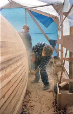 Sanding the hull smooth ready for sheathing
The first stage of which is to sand it smooth with light, sweeping strokes of a rotary sander—a very dusty process involving a facemask and a prolonged shower afterwards.
This serves two purposes:
- It removes any surplus epoxy from the planking process, and
- It provides a key for the epoxy glass rovings
The bi-axial rovings come in 4' (1.22m) wide rolls, so there'll have to be some provision for the additional thickness where they overlap.
Once the sanding process was complete, we marked these positions on the hull and ground them out a little with the sander to accommodate the additional thickness of the overlap.
Finally the entire hull surface received the attention of a household vacuum cleaner and then wiped over with Tack Rags to remove any remaining dust. We're ready to start sheathing the hull...
Sheathing with Bi-Axial Woven Rovings
The sheathing process itself was very much a team affair; it went like this:
- One person cuts the 4ft (1.3m) wide bi-axial woven rovings to length;
- another person mixes up the two-part epoxy;
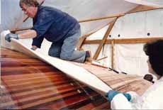
- another applies the resin to the hull, lays the rovings upon it (much like wall papering) and rolls it with a metal washer roller until all the air pockets are gone and the rovings are fully wetted out.
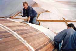 Sheathing the hull with woven rovings and epoxy
This process was carried out one hull side at a time, and once the epoxy had fully cured the overlapped join along the centreline was further reinforced by another layer of the woven glass bi-axial rovings.
We now had a hull that was impervious to both water and the most persistent of gribble worms and other marine borers.
Just one more thing to do before we turned the hull over and glassed the inside—fairing...
Fairing the Hull
Hulls built using this cedar strip boat building technique require very little fairing—much less so than would a steel or ferro-concrete hull, but they do require some.
The fairing compound is once again an epoxy product; this time the usual two-part product of resin and hardener, plus a micro-balloon low-density filler.
Before this is applied the entire hull must be abraded to remove any shininess and provide a sound base for the epoxy fairing compound to key into the epoxy glass surface.
Fairing is done with long sandpaper-covered flexible plywood boards, swept diagonally over the hull to avoid creating flat spots until passing the critical eyeball test.
Next, the Interior...
Finally, the hull is braced internally, removed from the shed, turned over with a crane (a hair-raising, buttock-clenching process that I didn't enjoy at all), and reinserted into the shed the right way up.
Now we could start the next stage of this cedar strip boat building project; glassing the interior surface of the hull and installing the bulkheads.
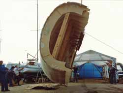 Turning the cedar strip hull over—a nervous moment...
Cutting & Installing the Plywood Bulkheads
With Alacazam's hull now sheathed externally, the next stage of building a wood boat can begin. Some builders of wood-epoxy boats don't sheath inside the hull above the heeled waterline, choosing instead to varnish the cedar strip planking.
Whilst there's no doubt that this approach provides a very attractive and natural finish to the visible cabin sides, we decided on maximum structural integrity by fully sheathing the hull internally with bi-axial rovings up to the underside of the deck.
Several additional layers of epoxied woven glass rovings and heavy tape were added along the centreline, and yet more still where the keel would eventually be 'letter-boxed' through the hull and bonded to the floors.
There'll be no troublesome keel bolts to worry about in this boat.
Bulkhead Locations
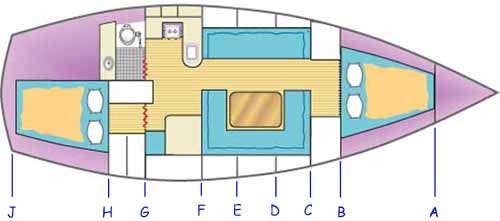 Locations of the structural bulkheads in Alacazam
Bulkhead A: This is a collision bulkhead in the bows of the boat forward of which is the anchor locker, below which is a watertight chamber.
Bulkhead B: This is a full bulkhead through which access is gained to the forecabin.
Bulkhead C: This is also a full bulkhead at the forward end of the saloon through which access is gained to the sail locker to port and cave lockers to starboard.
Bulkhead D: This is a double thickness partial bulkhead in the saloon providing support to the side decks and coachroof, and which carries the chainplates for the forward lower shrouds.
Bulkhead E: This is another beefed-up partial bulkhead, supporting the side decks and coachroof, spanned by a mahogany deck beam which carries the chainplates for the cap shrouds.
Bulkhead F: This is another beefed-up partial bulkhead at the forward end of the galley/navigation area, supporting the side decks and GRP cabin top and which carries the chainplates for the aft lower shrouds.
Bulkhead G: This is a full bulkhead at the companionway through which access is gained to the engine compartment, the heads to port and a hanging locker to starboard.
Bulkhead H: This too is a full bulkhead through which access is gained to the bosun's locker to port and the after-cabin to starboard
Bulkhead J: The transom, the top of which carries a mahogany beam to which the mainsheet track is bolted. A final small bulkhead right aft is a double-thickness collision bulkhead which forms the swim platform (see pic at bottom of this page) and carries the chainplate for the backstay and the runners.
Cedar strip boat building using the wood-epoxy technique results in an extremely strong hull, as not only are the bulkheads fully bonded to the hull sides and the deck, every part of the internal structure—lockers, bunk berths, seats, galley units and the like are all fully bonded to the bulkheads and hull sides too. I'm a real fan of building a wood boat in this way.
Cutting & Installing the Ply Bulkheads
The bulkheads were cut from half-inch marine ply.
Their shape had been developed by the 'AutoCad' software design package which provided us with co-ordinates from which to draw them full size directly onto the 8 foot by 4 foot (2.44m x 1.22m) sheets of ply.
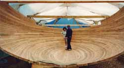 Would you care to dance?
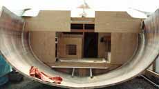
At 12' 5" wide (3.9m) Alacazam's hull is fairly beamy, but not quite as cavernous as this wide-angle picture suggests.
Nevertheless the standard size ply sheets weren't going to be large enough individually, so they were epoxy glued together with an 8:1 scarfed joint as necessary.
Those sections of the bulkheads that would eventually take chainplate loads or keel loads were doubled up in thickness. The bulkheads were cut with a small clearance such that high-strength epoxy filled could be forced through from one side to the other, eliminating the possibility of any hard spots between the hull and the bulkheads.
They were held in position until the epoxy had set by driving in panel pins along each side, which were covered by a fillet of structural filler along both sides of the joint.
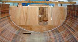 She's coming along nicely!
Finally the fillets were covered by epoxy-glass tape, forming a massively strong hull to bulkhead joint.
With all bulkheads complete (other than the transom, which was left out for as long as was practical to permit easy access into the hull), we were ready to start forming the other elements of the internal structure.
But before we move away from the bulkheads, here's a 'lesson learned'...
We should have cut limber holes (in inverted U-shapes) in the bulkheads before we glassed them in. We didn't, and consequently had to cut them out later with a hole saw.
This meant that the last inch or so of bilge water can't flow through to the keel sump where the automatic bilge pump can deal with it. Alacazam's a dry boat—we only get water in the bilge when we pull the thru-hull log impeller for de-barnacling, or bleeding the shaft seal, or I'm a bit careless when filling the water tanks.
But now we have to sponge out the bilges where this collects. No big deal, but irritating nonetheless.
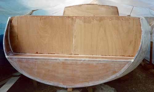 The hull is finally closed in with the completion of the transom
It was only after completing all the interior structure, the deck, coachroof and cabin top were we able to fit Alacazam's final bulkhead at the transom.
Building the Interior Structure
We're at the stage where the western red cedar strip hull is complete and the bulkheads have been bonded in. Now it's time to make a start on the internal structure.
All major elements of the internal structure—bunk berths, cabin seating, floors, cabin sole, navigation area, galley, engine box and lockers—will be fabricated from half-inch (12mm) marine ply and bonded into the hull in exactly the same way as we built-in the bulkheads.
As a result the entire hull will be an immensely strong monocoque, with every component acting as a structural member.
In my view there's no better way of building a wooden boat than using modern wood-epoxy techniques.
The Interior Structure
Alacazam's design brief was for a reasonably quick long-distance cruising sailboat, easily maintained and handled by a cruising couple.
At just 38 feet (11.5m), space would be at a premium and would have to be used wisely.
We'll start at the bow and work our way aft...
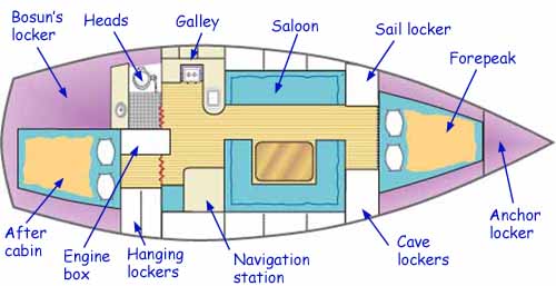 Alacazam's internal layout
The Anchor Locker
We opted to have the anchor locker right forward, draining through limber holes in the hull sides rather than into the bilge.
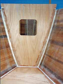 We built in a collision bulkhead and watertight chamber beneath the anchor locker
Access to it, should you ever need to sort the chain out, is through a hatch (not yet fitted here).
There are arguments against an anchor locker in this location, with much to be said for having the weight of the chain closer to the waterline—better still, below it—and further aft.
But I didn't want to live with the unpleasant odours of seabed ooze permeating from the bilge that often accompanies such an arrangement.
The space under the locker and forward of the first bulkhead is completely sealed—a valuable safety feature in the event of being holed below the waterline at the bow.
The Forepeak Berths
At 7' 2" (2.2m) long, these are good berths for our guests when in harbour or at anchor, but not much use at sea in anything other than very light conditions.
These were constructed as vee berths with an infill panel for use in the event that their occupants be keen to cosy up.
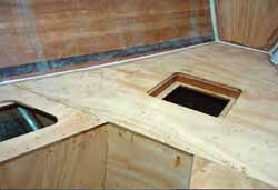 The storage space beneath the forepeak berths is accessed through a watertight hatch (not yet fitted here)
The space forward and below of the infill is a storage locker with a watertight hatch (not yet fitted here), creating another sealed space in the event of collision damage.
The spaces below the 'head' ends either side of the infill are separate stowage lockers with lift out top panels.
The Sail Locker & Cave Lockers
The sail locker provides stowage for Alacazam's sail wardrobe—mainsail, staysail, yankee, genoa, storm jib, trysail and asymmetric spinnaker.
The foredeck hatch will enable the spinnaker sock to be hoisted directly out of the locker.
Opposite, on the starboard side, is a sole-to-deck bank of cave lockers.
This will have lift-out 'doors', as in my experience, hinges on fold-down doors are prone to failure.
The Saloon
The berths, which will be fitted with leecloths, are 7' 2" (2.2m) long and parallel to the centreline making them ideal seaberths.
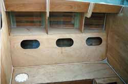 The saloon seating will be fitted with lee-cloths to provide additional secure sea-berths
We resisted, without much difficulty, any temptation to have curved seating or individual chairs in the saloon.
Not only would these be impractical for seating when heeled, it would rule out any chance of using them as seaberths when underway.
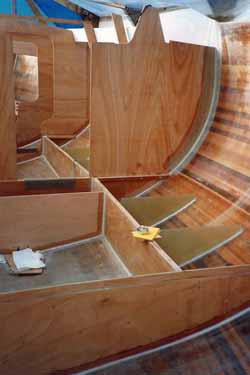 The water ballast tanks under the saloon seating are fitted with fibreglass baffle plates
Behind the seat backs are lockers, and above them and outboard are bookshelves, plus what will eventually become a booze locker on the port side.
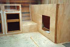
Nothing unusual there, but below the seats—where stowage lockers would normally be—we have water ballast tanks, which is unusual for a cruising boat.
There will be two each side, each capable of water transfer from one side to the other or of being filled and drained independently. They extend for the saloon into the galley/navigation area.
The watertight access hatch to the port tank can be seen in the picture above.
Fibreglass baffle plates were bonded into each tank to reduce the free surface area and limit any sloshing about.
Of course a waterballast system would involve a considerable amount of plumbing, all of it competing with space for the head and holding tank, cabin heating, hot water system, watermaker and gas installation. We had to make sure there was space for all it before we went much further.
Constructing the Deck & Coach Roof
What has been very noticeable about this cedar strip boat building project so far is the speed at which the hull is coming together. This is largely the result of choice of hull material and building technique; cedar strip and wood-epoxy.
Alacazam's cedar strip hull was constructed upside down over temporary chipboard frames. Once this stage of her construction was complete, she was righted, the temporary frames removed and the marine ply structural bulkheads bonded in.
Then the other plywood components of the internal structure; floors, the cabin sole, bunk berths and saloon seating, lockers, the engine box and finally the galley and navigation area were built-in.
Now it's time to put the lid on...
Constructing the Deck
Perhaps the obvious choice of deck material for a wooden boat would be teak; but it wasn't for us. Teak is heavy, needs to be looked after, and doesn't like being exposed to long periods of tropical sunshine.
Marine ply on the other hand, sheathed in epoxy glass cloth and coated with non-slip paint was a much more practical solution for our cedar strip boat building project, so that was the one for us.
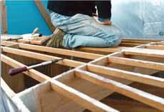
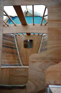 The king plank and stringers go in
But before we get to lay the deck we have to build the support structure for it; the king plank, the longitudinal stringers and deck beams—all of which were fashioned from mahogany.
With these in place the half-inch (12mm) thick marine ply deck (scarfed as necessary) was screwed and epoxied to them and into the top of the 1" (25mm) hull planking.
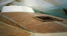
Incidentally, the bare edges of the plywood that you can see in this picture won't stay like that for much longer; they'll be fitted with cherry trim and varnished.
The whole deck area (foredeck, sidedecks and cockpit coamings) was then sheathed in epoxy glass woven rovings before filling, fairing and painting.
The glass cloth was carried over the hull-to-deck joint and onto the hull side. That's one hull-to-deck joint that's never going to leak.
Fabricating the Coachroof
When we cut the cedar planks for Alacazam's hull we were left with a number of thinner strips; these were now to put to good use. A run through the planer to get them to a uniform thickness and they were perfect for construction the coachroof. Here's how we did it...
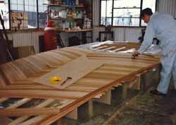 Laminating the mahogany coachroof
First we made a built a framework to act as a former, covered it with polythene and laid the cedar strips diagonally outward and aft from the centreline as shown here.
The strips were glued on to the other, the polythene preventing any adhesion to the frame, and lightly tacked to it with panel pins.
Once the glue had set we removed the pins, lightly sanded the cedar, vacuumed the dust off it, then tack-ragged it.
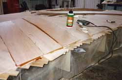 Finishing off with diagonal strips of ply
Next we cut strips of 8mm marine ply and glued and stapled (stainless steel staples, of course) these to the cedar, before sheathing it with epoxy glass cloth.
The edges were then trimmed to shape and the coachroof was done.
Laminating the main deck beam
The next stage was to laminate-up a mahogany deck beam to support it, and to provide lateral support for the cap shroud chainplate knees.
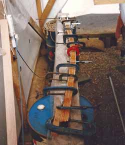 Laminating the main deck beam
With the beam in place, the coachroof was attached to it and the deck and other supporting structure by the usual process of screwing it down onto a bed of high-strength epoxy gloop, then bonding the joints with woven glass tape and epoxy.
The eagle-eyed amongst you will notice the join down the centreline that wasn't there when it was in the workshop. Something to do with the width of the coach roof and the size of the workshop door...
With the coachroof in place, and all joints filled and faired with high-strength epoxy filler, both the deck and the coachroof were now complete.
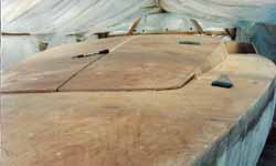 The coach roof meets the foredeck
The chevroned cedar deckhead in the saloon looked great and like the rest of this one-off design, unique.
The fitting of the deck and coachroof marked a significant point in this cedar strip boat building project.
From here on in the focus would be on the GRP elements of Alacazam's composite structure—the cabin top, cockpit and keel—all of which we would be creating ourselves.
Moulding the GRP Cabin Top
We've reached the stage in this cedar strip boat building project in which we move away from building in western red cedar strip and marine ply. Now the composite element of Alacazam's construction begins; time to reach for the chopped strand mat and polyester resin.
Why? Well for the remaining components required to make the hull structure complete—primarily the cabin top, sliding hatch and garage, and cockpit—we've decided to construct them in GRP (Glass Reinforced Plastic), or fibreglass as it's often called.
This is quite a complex process, as for each one we need to make a mould. And for those that require a female mould—like the cabin top for example—we'll need to make a plug, from which we make a mould, from which we mould the cabin top. See, I told you it was complex.
Hers's how we set about it...
The GRP Cabin Top Moulding
The cabin top is located over the galley and navigation area and will provide all-round vision from below.
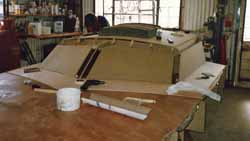 The initial stage of making a plug for Alacazam's cabin top
And as the forward edge and the sides of the cabin top will sit on the coachroof we used the coachroof as the base for the cabin top plug before it came out of the workshop.
That way the GRP cabin top would fit perfectly. Wouldn't it?
Making the Plug
Chipboard was the main building material for the plug, as you can see in the above image.
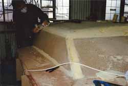 The plug for the cabin top mould progresses...
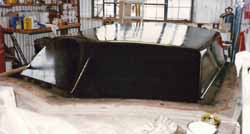 Done!
Done!The rounded edges of the plug were formed with expanding polyurethane foam as used in the building industry, and sanded to shape.
The entire plug was then filled and faired, and finally given a coat of black mould release agent.
Making the Mould
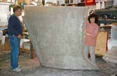
With the cabin top plug complete, the cabin top mould was then laid-up in chopped strand mat and polyester resin, to form the GRP mould as somewhat proudly exhibited here.
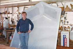 The designer poses with the completed mould...
Foam core material was incorporated in the lay-up to provide sufficient stiffness for the mould to keep its shape.
The Cabin Top Emerges
Finally, the cabin top was laid-up in the female mould and later emerged as the finished moulding.
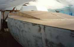 The GRP cabin top moulding fitted on Alacazam's coachroof
As expected it fitted Alacazam perfectly, where it was screwed and epoxied to the coach roof.
With the smooth gelcoat on the outside of the finished moulding, the less attractive inside would later be covered with mural mousse headlining material.
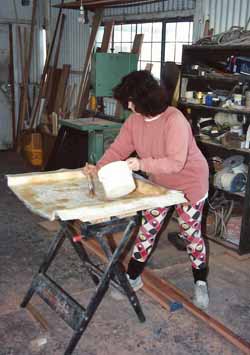 Mary lays-up Alacazam's sliding hatch cover. Where did she get those pants?
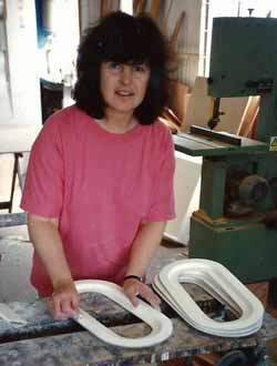 More of Mary's handiwork—the GRP frames for the portlights
In the meantime, Mary was laying-up the fiberglass sliding hatch and garage, and the non-opening portlights for the hull sides aft. These would later be glazed with panes cut from clear polycarbonate sheet, and provide light in the heads, bosun's locker and aft cabin.
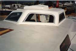 Looking good!
Cutting out the holes in the cabin top for the custom-designed windows was another one of those tasks filled with anxiety.
But with the hatch and the windows fitted (manufactured to order by Seaglaze Marine Windows), I think we could be rightly proud of the final result...
The Cockpit Moulding
In a self build boat as in any other sailboat, whether intended for cruising or racing, good cockpit design is fundamental to the overall success of the boat; particularly the slope of the seatbacks, the width of the seats and the distance across the cockpit well.
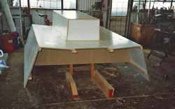 The mould for Alacazam's GRP cockpit
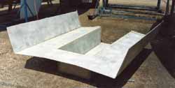 The completed cockpit moulding
These were all taken account of in Alacazam's cockpit, the mould for which was fabricated in melamine-faced chipboard.
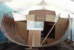 Installing the GRP cockpit moulding
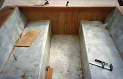 Hey, we've got a cockpit!
It all looked a little precarious until properly built in. You'll notice an absence of cockpit lockers. I'm not a fan of these, owing to an incident one night sailing single-handed around Cape Trafalgar in my Nicholson 32, Jalingo 2.
Briefly, I was head down in the cockpit locker looking for some warps to tow astern (it was blowing a bit) when we were pooped. About half a ton of water filled the cockpit, much of which ended up in the cockpit locker which did little help my state of anxiety. It won't happen with Alacazam.
And finally...
The last GRP moulding we had to do was the top opening fridge which was later installed in the galley with 4" (100mm) insulation all round.
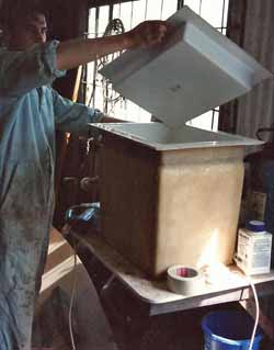 The bespoke GRP top-opening fridge takes shape
Well, actually it wasn't quite the last fibreglass component we had to deal with in this self build boat project. There was the lead-filled GRP encased bulb keel to be built, and this wasn't going to be easy...
Fitting the Bulb Keel
Making a bulb keel for our wood epoxy sailboat Alacazam represented something of a challenge. It had to be of an efficient hydrodynamic design to properly optimise the lift-to-drag ratio whilst getting the ballast down as low as possible.
The designer, Andrew Simpson, rose to the challenge as usual and came up with a design for a medium aspect ratio foil that promised good performance and stability characteristics for a fast cruising boat.
Long enough to provide good tracking ability and deep enough to generate an adequate righting moment; it looked good, particularly with that racy-looking bulb.
Incidentally some torpedo like bulbs project forward of the leading edge of the keel, where they're ideally placed to collect mooring lines and fishing nets. Not a wonderful idea for a cruising boat keel.
So how did we convert that on-screen image into a real life bulb keel? Read on...
Forming the Bulb Keel in Polystyrene
After making due allowance for the thickness if the GRP casing we drew the foil templates on polystyrene sheets and built the keel up by stacking one on top of the other, totally forgetting to take any photographs unfortunately.
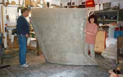 Alacazam's GRP bulb fin keel takes shape
This was sanded to shape and the GRP skin laid up in layers of chopped strand mat and woven glass cloth using vinyl ester resin.
Once cured, we dug out as much of the polystyrene as when could by hand, finally have to complete the process by dissolving it with petrol. Nobody smoked...
You can see that the GRP keel only included the top part of the keel bulb—the part that provided the end plate effect. To the lower half, a solid lead casting would be attached—once we'd moved the keel out of the workshop.
Building the Bulb Keel into the Hull
The technique is to poke the keel up through an appropriately shaped slot in the bottom of the hull and bond it to the floors, the beam that carries the mast loads, and the bilge.
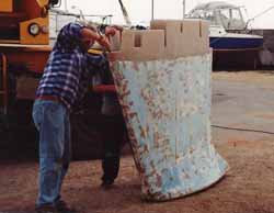 Cutting the slots in the GRP keel before bonding into Alacazam's hull
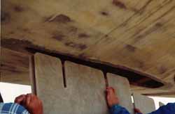 The moment of truth...
Cutting the slot in the hull and the notches in the top of the keel provided a ominous opportunity for a spectacular screw-up. Measuring twice and cutting once was far too casual for me; I must have measured a dozen times—then checked, re-checked and re-re-checked. It fitted perfectly...
Once the hull had been re-levelled horizontally and longitudinally and the keel adjusted for verticality, we filleted all joints with high-strength epoxy filler. All joints were then heavily reinforced with layers of epoxy glass woven rovings.
Adding the Ballast
The ballast took the form of lead ingots. These were arranged in layers and all voids filled with a mixture of lead shot and epoxy resin.
Each layer was covered with this mixture to form a bed for the next layer of ingots and the process repeated. We didn't completely fill the keel; a sump was left to collect and bilge water that would drain into it through limber holes drilled the keel.
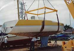 Lifting Alacazam onto her solid lead keel bulb
The remaining half of the bulb was cast in solid lead using a sandbox mould. Once completely cooled this was sheathed in glass mat to provide a bond for the next part of the process.
The boat had to be lifted by a crane, the lead casting levered into position below it—a process involving crowbars, sweat and a lot of grunting and bad language—before coating the top of the bulb with high-strength epoxy gloop.
Then the boat was lowered onto it, squeezing out any surplus gloop.
Finally the two parts of the keel bulb were bonded together with layers of epoxy glass rovings, and later filled and faired.
And that was it; job done. We now had a bulb keel securely attached to the hull.
Making the Rudder
 perhaps not...
A typical productions boat's rudder is likely to have been fabricated as shown here, with two GRP mouldings 'clamshelled' around a foam core.
Not the most reliable arrangement you might think—and you'd be right.
We wanted something a little more robust for Alacazam's rudder.
 Stainless steel internals...
But first, the rudder stock.
We fabricated this from a 2" (50mm) diameter stainless steel solid bar and welded on flat stainless tangs that would be embedded within the rudder.
The Admiralty Bronze casting will eventually connect the rudder to the skeg.
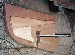 Taking shape...
With the rudder stock fabricated, we began the construction of the rudder core.
It was made up from half inch (12mm) marine ply sheets, cut to shape and incorporating cut-outs for the tangs, screwed and glued together.
The rudder and skeg was built up as a single unit at this stage.
The rudder design software generated coordinates for various stations along the rudder, and we used these to cut templates so that we could get the shape right.
Shaping the rudder profile was done by hand, initially with a plane to remove the excess, then with a file and diminishingly coarse grades of sandpaper.
Once the rudder profile matched the appropriate template we removed the section that would form the skeg.
Next, the rudder was fitted to the stock with any gaps between the tangs and the ply taken up with high-strength epoxy 'gloop'.
Finally both the rudder and the skeg were sheathed in several layers of epoxy-glass rovings before being filled and faired with epoxy fairing compound.
Fitting the Rudder
The skeg was letter-boxed through a slot cut in the hull, securely braced internally and bonded to it with fillets of high-strength epoxy and epoxy glass rovings.
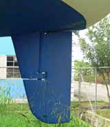 The finishhed rudder
Inside the hull we had constructed a GRP tube to contain the stock, and the skeg was also bonded to the lower end of that.
The rudder was then securely fitted to the stock via the bronze bearing, and located at the top of the rudder by a stainless steel bearing.
That's it, we now have a very robust and efficient rudder securely attached to Alacazam's hull.
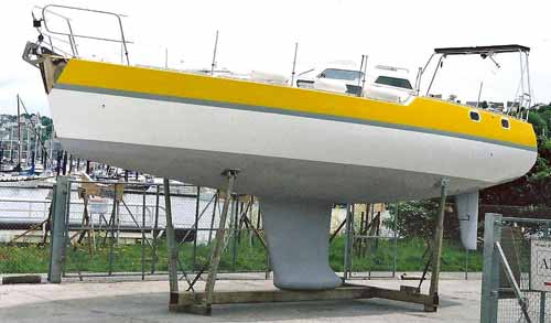 Wow!
Wow!Recent Articles
-
Expert Guide: Picking up a Mooring in All Conditions & Tide
Jan 29, 26 09:17 AM
Master the technical skills for picking up a mooring buoy. Expert advice on approach angles, boat handling, and heavy weather security for offshore sailors. -
Self-Tacking Headsails: A Guide for Offshore Sailors
Jan 28, 26 11:58 AM
Master the mechanics of self-tacking headsails. Learn about track geometry, sheeting angles, and offshore performance for shorthanded crews. -
Olson 35 Sailboat Review: Specs, Performance & Cruising Analysis
Jan 27, 26 03:39 PM
A comprehensive review of the Olson 35 sailboat. Explore design ratios, performance analysis, and detailed specifications for this iconic George Olson cruiser-racer.
